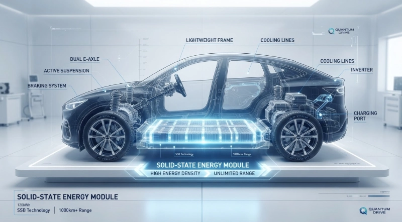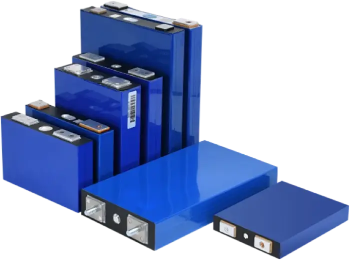










What Material Choices Affect Battery Performance
Release time: 2026-06-23
Table of Contents
The global transition toward electrification, spanning electric vehicles (EVs), grid-scale energy storage systems (ESS), and portable electronics, has placed electrochemical energy storage at the center of modern technological development. At the heart of this transition lies a fundamental engineering challenge: optimizing the battery cell. A battery is not a static repository of electricity; it is a dynamic, highly complex electrochemical system where macroscopic output is entirely dictated by microscopic material interactions.
When designing or procuring energy storage systems, understanding the underlying chemistry is crucial. Various mechanical, thermal, and chemical variables act as the primary battery performance factors that determine whether a system will succeed or fail in its target application. To unlock higher energy densities, faster charging rates, prolonged cycle lives, and uncompromising safety standards, scientists and engineers must continuously push the boundaries of materials science. This comprehensive analysis explores how the strategic selection of cathode, anode, electrolyte, separator, and current collector materials fundamentally shapes the operational limits of modern batteries.
1. The Core Architecture of Modern Electrochemical Cells
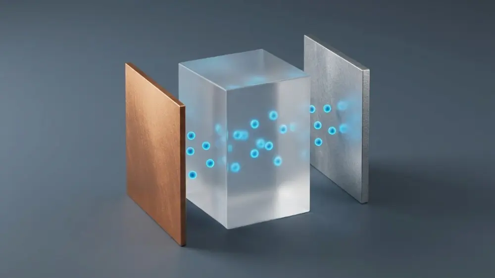
An electrochemical cell operates on the principle of controlled oxidation-reduction (redox) reactions. During discharge, active ions (typically lithium ions, Li⁺) migrate internally from the negative electrode (anode) to the positive electrode (cathode) through an ionically conductive medium (electrolyte), while electrons traverse an external circuit to perform electrical work. During charging, an external power source reverses this flow.
The thermodynamics of this system are governed by the Gibbs free energy change (ΔG) of the active chemical couples, which directly determines the nominal cell voltage (E) through the fundamental relation:
ΔG = −nFE
Where:
- n is the number of moles of electrons transferred per mole of reaction,
- F is the Faraday constant (≈ 96,485 C/mol),
- E is the electromotive force or equilibrium cell voltage.
To construct a high-performance cell, engineers must carefully evaluate the chemical properties of all internal components. The structural integrity, chemical stability, and electronic/ionic conductivity of these battery materials directly determine the cell’s capacity, power capability, safety profile, and manufacturing cost. Every component must be meticulously engineered to withstand thousands of lithiation and delithiation cycles without undergoing catastrophic structural degradation or parasitic side reactions.
2. Cathode Materials: The Energy Density Engine
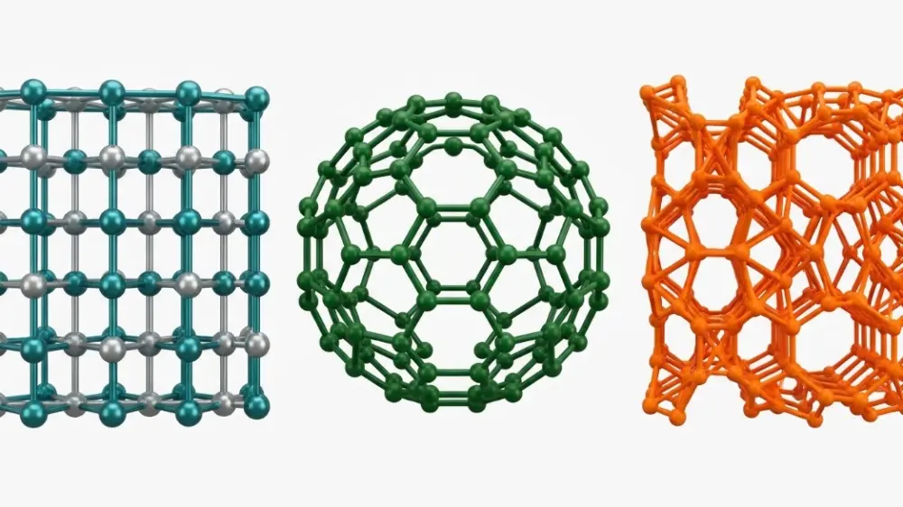
The cathode (positive electrode) is historically the most expensive and performance-limiting component in a lithium-ion battery. It acts as the primary reservoir for lithium ions and fundamentally dictates the cell’s nominal voltage and specific energy density. Cathode materials generally fall into three distinct crystallographic structures: layered transition metal oxides, olivine phosphates, and spinel oxides.
Cathode Crystalline Structures At a Glance:
- Layered Oxides (e.g., NMC, NCA, LCO) — High Energy Density, rapid 2D lithium-ion diffusion.
- Olivine Phosphates (e.g., LFP / LiFePO₄) — Superb Safety & Long Life, highly stable covalent bond framework.
- Spinel Oxides (e.g., LMO, LNMO) — Excellent C-Rates & Power Output, 3D network channels for quick transport.
Layered Transition Metal Oxides (LiMO₂)
Layered oxides, where M represents transition metals like Cobalt (Co), Nickel (Ni), Manganese (Mn), or Aluminum (Al), feature a two-dimensional interstitial framework that allows rapid lithium-ion diffusion.
- Lithium Cobalt Oxide (LiCoO₂ or LCO): The pioneer material for commercial lithium-ion batteries. LCO offers high volumetric energy density, making it ideal for smartphones and laptops. However, its high cobalt content presents severe ethical, supply-chain, and cost challenges, and its thermal instability at high states of charge limits its use in high-power applications.
- Nickel-Manganese-Cobalt (LiNiₓMn_yCo_zO₂ or NMC): By adjusting the ratio of Nickel, Manganese, and Cobalt, engineers can customize performance. Nickel increases energy density but reduces thermal stability; manganese provides structural stability; cobalt stabilizes the layered structure and enhances electronic conductivity. Modern variations like NMC 811 (80% Ni, 10% Mn, 10% Co) maximize capacity but require advanced surface coatings and dopants to prevent structural degradation, such as the detrimental phase transition from the rhombohedral to the rock-salt phase at high voltages.
- Nickel-Cobalt-Aluminum (LiNiₓCo_yAl_zO₂ or NCA): Similar to high-nickel NMC, NCA delivers high specific energy (commonly used in electric vehicles) by replacing manganese with aluminum to stabilize the structure under high-voltage operations.
Olivine Phosphates (LiMPO₄)
- Lithium Iron Phosphate (LiFePO₄ or LFP): LFP has emerged as a dominant chemistry for stationary energy storage and cost-sensitive electric vehicles. The phosphorus-oxygen bonds in the PO₄³⁻ tetrahedral framework are highly covalent, forming a stable olivine structure. This stable molecular structure ensures that LFP does not release oxygen upon thermal decomposition, dramatically reducing the risk of thermal runaway.
The primary half-reaction during charge is:
LiFePO₄ ↔ FePO₄ + Li⁺ + e⁻
The major trade-offs of LFP are its relatively low nominal voltage (3.2 V vs. Li/Li⁺ compared to NMC’s >3.7 V) and lower electronic conductivity, which requires nano-sizing and carbon-coating of the LFP particles to facilitate acceptable electron transport.
Spinel Oxides (LiM₂O₄)
- Lithium Manganese Oxide (LiMn₂O₄ or LMO): Spinel structures feature a three-dimensional network of channels that permits rapid lithium-ion transport, enabling high C-rates (high power delivery). However, LMO suffers from manganese dissolution into the electrolyte at elevated temperatures due to the Jahn-Teller distortion in Mn³⁺ ions, which leads to rapid capacity fade.
| Cathode Chemistry | Crystal Structure | Nominal Voltage (V) | Specific Capacity (mAh/g) | Thermal Runaway Temp (°C) | Relative Cost | Primary Applications |
|---|---|---|---|---|---|---|
| LCO (LiCoO₂) | Layered | 3.7 – 3.9 | 140 – 150 | ≈ 150 | High | Consumer Electronics |
| NMC 811 | Layered | 3.7 – 3.8 | 180 – 200 | ≈ 210 | Medium-High | Electric Vehicles, High-End Tools |
| NCA | Layered | 3.7 – 3.8 | 180 – 200 | ≈ 180 | Medium-High | EVs, Medical Devices |
| LFP (LiFePO₄) | Olivine | 3.2 | 150 – 160 | > 270 | Low | Electric Buses, Grid Storage, LFP EVs |
| LMO (LiMn₂O₄) | Spinel | 3.8 | 100 – 110 | ≈ 250 | Low | Power Tools, Hybrid Vehicles |
3. Anode Materials: Fast Charging and Cyclic Longevity
While the cathode defines the upper limit of the cell voltage, the anode (negative electrode) acts as the host for lithium storage during charging. The electrochemical potential of the anode must be as close to 0 V vs. Li/Li⁺ as possible to maximize cell voltage, but not so low that it triggers metallic lithium plating, which can cause internal short circuits and catastrophic safety failures.
Graphite
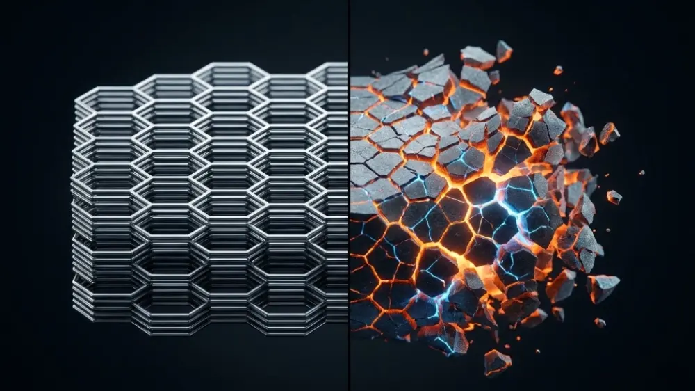
Graphite remains the industry standard anode material. It features a layered hexagonal structure where lithium intercalates between graphene sheets to form LiC₆ at full charge:
Li⁺ + e⁻ + 6C ↔ LiC₆
Graphite exhibits low volume expansion (≈ 10%) during cycling, providing a stable structure that can last for thousands of cycles. However, its theoretical specific capacity is limited to 372 mAh/g. This physical limitation prevents significant further increases in energy density.
Silicon and Silicon-Graphite Composites
Silicon represents a highly promising alternative anode material, offering a massive theoretical specific capacity of approximately 3579 mAh/g (based on the formation of the Li₁₅Si₄ alloy phase at room temperature). However, silicon anodes undergo extreme volumetric expansion and contraction (≈ 300%) during lithiation and delithiation cycles.
Anode Material Expansion Comparison:
- Graphite Anode: Minimal volumetric expansion (~10%), resulting in a highly stable SEI (Solid Electrolyte Interphase) layer.
- Silicon Anode: Extreme volumetric expansion (~300%), leading to a cracked SEI, active lithium loss, and particle pulverization.
This severe breathing effect leads to mechanical pulverization of the silicon particles, electrical isolation from the current collector, and the continuous destruction and reformation of the Solid Electrolyte Interphase (SEI) layer. This continuous reformation rapidly consumes active lithium and electrolyte, leading to premature cell death. To mitigate this issue, modern battery material selection strategies focus on incorporating small percentages (5% – 15%) of silicon nanoparticles or silicon-carbon (Si-C) composites into graphite matrices, balancing increased capacity with cycle life.
Lithium Titanate (Li₄Ti₅O₁₂ or LTO)
LTO is a spinel-structured anode material that operates at a relatively high potential of 1.55 V vs. Li/Li⁺. Because of this high potential, LTO completely avoids SEI formation and lithium plating, rendering it exceptionally safe. Furthermore, LTO is a “zero-strain” material, experiencing less than 1% volume change during cycling. This exceptional structural stability enables a lifespan exceeding 20,000 cycles and extremely high fast-charging capabilities (up to 10C or more). The primary trade-off is low cell energy density, which limits LTO to specialized applications such as heavy-duty transit, rail, and stationary backup power.
4. Electrolytes: The Ion Transport Medium
The electrolyte serves as the physical barrier to electrons but the highway for ionic transport. It must exhibit high ionic conductivity (σ > 10⁻³ S/cm), near-zero electronic conductivity, a wide electrochemical stability window (remaining inert across the operating potentials of both anode and cathode), and excellent thermal stability.
Liquid Organic Electrolytes
Traditional lithium-ion batteries utilize liquid electrolytes consisting of a fluorinated lithium salt, typically lithium hexafluorophosphate (LiPF₆), dissolved in a mixture of cyclic and linear organic carbonate solvents (e.g., Ethylene Carbonate [EC], Dimethyl Carbonate [DMC], and Diethyl Carbonate [DEC]).
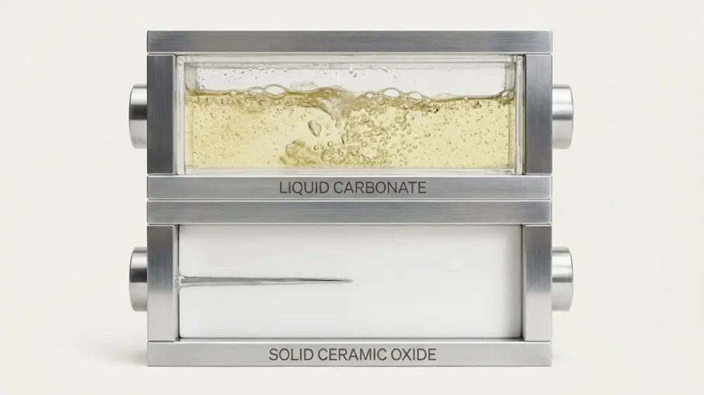
While highly effective at conducting ions at room temperature, liquid carbonates are volatile, flammable, and susceptible to thermal runaway. If a cell is punctured or overheats beyond its safety threshold, the organic solvents undergo exothermic combustion, reacting violently with released oxygen from a decomposing cathode. Therefore, electrolyte material impact on battery safety and operational temperature limits is a critical focus for safety-conscious system designers.
Solid-State Electrolytes (SSEs)
Solid-state batteries replace volatile liquid electrolytes with solid ion conductors, promising to revolutionize battery safety and energy density. SSEs are broadly categorized into three distinct families:
- Inorganic Sulfides (e.g., Li₁₀GeP₂S₁₂ [LGPS], Argyrodites): Sulfides offer exceptional ionic conductivity, sometimes exceeding that of liquid electrolytes (≈ 10⁻² S/cm at room temperature). They are relatively soft, allowing for excellent interfacial contact under pressure. However, they are highly sensitive to moisture, reacting to produce highly toxic hydrogen sulfide (H₂S) gas, which complicates manufacturing.
- Inorganic Oxides (e.g., Li₇La₃Zr₂O₁₂ [LLZO], LATP): Oxides are chemically stable, highly resistant to dendrite penetration, and completely non-flammable. However, their brittle ceramic nature makes processing difficult and introduces high interfacial resistance, requiring high temperatures or high stack pressures to operate effectively.
- Solid Polymer Electrolytes (e.g., Polyethylene Oxide [PEO] doped with lithium salts): Polymers are easy to manufacture using roll-to-roll processes and are highly flexible. However, their ionic conductivity at room temperature is exceptionally low, typically requiring operation at elevated temperatures (>60°C) to facilitate adequate ion transport.
Solid-State Electrolyte (SSE) Families At a Glance:
- Inorganic Sulfides: Highest ionic conductivity, soft and ductile for good contact, but highly moisture sensitive.
- Inorganic Oxides: Maximum structural safety, completely non-flammable, but brittle ceramic nature with high interface resistance.
- Solid Polymers: Excellent flexibility and scalable production, but very low room-temperature conductivity (needs heat >60°C).
5. Separators and Current Collectors: The Passive but Critical Components
While cathodes, anodes, and electrolytes are active participants in charge storage, passive components like separators and current collectors are equally critical to preventing self-discharge, electrical shorting, and mechanical failures.
Separators
The separator is a thin, microporous polymeric membrane positioned between the anode and cathode. It must prevent physical contact between the electrodes while allowing the free flow of solvated lithium ions.
- Polyolefin Membranes: Most commercial batteries utilize single or multi-layered microporous films made of Polyethylene (PE) or Polypropylene (PP). These polymers are selected for their chemical inertness and mechanical strength.
- Thermal Shutdown Features: Multi-layered separators (e.g., PP/PE/PP) provide a safety shutdown mechanism. If the internal cell temperature reaches the melting point of PE (≈ 130°C), the PE pores melt shut, stopping ion transport and safely terminating the electrochemical reaction. The outer PP layers (melting point ≈ 165°C) remain mechanically intact to prevent physical contact and shorting.
- Ceramic Coatings: Modern high-performance separators are coated with sub-micron alumina (Al₂O₃) or silica (SiO₂) particles. These ceramic coatings dramatically improve wettability (ensuring uniform electrolyte distribution) and raise the thermal shrinkage resistance of the polymer up to 200°C, preventing catastrophic failure during thermal stress.
Current Collectors
Current collectors act as the bridge between the electrochemical active materials and the external terminals. They must possess high electronic conductivity, excellent electrochemical stability, and mechanical strength at thin profiles.
- Aluminum Foil (Cathode): Aluminum is universally used at the positive electrode. Although aluminum is thermodynamically unstable at high potentials, it forms a dense, thin passivation layer of aluminum oxide (Al₂O₃) or aluminum fluoride (AlF₃) when in contact with carbonate-based electrolytes containing fluorine. This protective passivation layer prevents further corrosion of the foil.
- Copper Foil (Anode): Copper is utilized at the negative electrode because it does not form alloys with lithium at low potentials (unlike aluminum, which quickly pulverizes if used at the anode). However, copper is susceptible to oxidation and dissolution if the cell is over-discharged below 1.5 V vs. Li/Li⁺. When a lithium-ion battery is drained to 0 V, copper ions can dissolve into the electrolyte and redeposit as metallic copper dendrites during subsequent charging, causing internal short circuits and safety hazards.
6. Balancing the Trade-offs for Custom Applications
There is no “perfect” battery chemistry. Battery design is fundamentally an exercise in multi-variable optimization, where changing one material parameter inevitably impacts other properties.
For instance, selecting high-nickel NMC cathodes coupled with silicon-graphite anodes yields maximum energy density, which is ideal for long-range electric vehicles. However, this combination requires complex thermal management systems and active safety controls due to its lower thermal runaway onset temperature. Conversely, selecting LFP cathodes with graphite anodes yields a lower-cost, highly durable, and safer system with a long cyclic life, making it highly attractive for commercial utility-scale solar and wind storage installations.
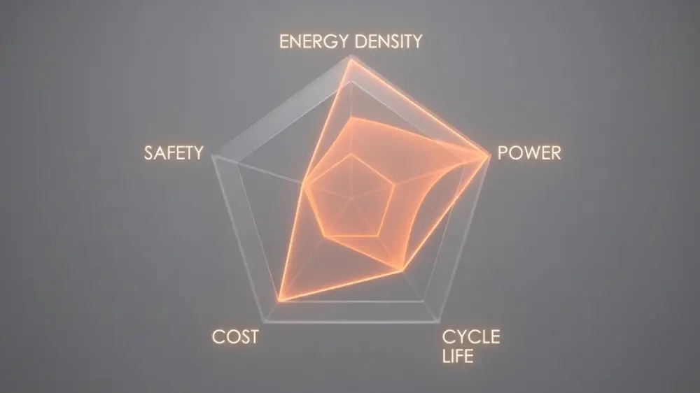
The Battery Design Pentagon Balancing Act:
- Capacity (Energy Density) vs. Safety (Thermal Stability)
- C-Rate (Fast Charging/Power Output) vs. Lifespan (Cycle Longevity)
- Cost (Raw Material & Manufacturing Economics)
- Changing one material choice shifts the entire balance of the pentagon.
The table below highlights how different system-level material configurations alter key battery performance factors:
| Design Goal | Target Chemistry (Cathode / Anode / Electrolyte) | Dominant Advantages | Major Trade-offs & Engineering Hurdles |
|---|---|---|---|
| Max Energy Density | High-Nickel NMC / Silicon-Graphite / Liquid Carbonate | Long driving range, compact volume | High materials cost, complex thermal management, shorter overall cycle life |
| Maximum Safety & Lifespan | LFP / Graphite / Liquid Carbonate | Low fire risk, lower cost, >4,000 cycles | Lower specific energy density, poorer sub-zero temperature performance |
| Ultra-Fast Charging (UFC) | NMC / Lithium Titanate (LTO) / Liquid Carbonate | Fully charged in under 6 minutes, >20,000 cycles | Exceptionally low energy density, high cost per Wh |
| Next-Gen Solid-State | High-Nickel NMC / Lithium Metal / Sulfide Solid Electrolyte | Volumetric energy density >1000 Wh/L, highly stable, non-flammable | High interfacial resistance, manufacturing scalability issues, high cost |
Ultimately, engineering teams must evaluate their specific use cases to guide their battery material selection process. For example, in grid-scale backup systems, footprint and weight are rarely primary constraints, making lower-cost LFP chemistry highly competitive. For high-altitude aerospace applications, weight is the overriding metric, justifying the premium cost of advanced high-nickel oxide chemistries or emerging solid-state systems.
As materials science continues to mature, we are transitioning from a trial-and-error discovery phase to a computational design paradigm. Machine learning algorithms and high-throughput DFT (Density-Functional Theory) computations allow researchers to simulate millions of virtual battery materials before synthesizing them in the laboratory. These computational advancements are dramatically accelerating the development cycle of next-generation batteries, bringing us closer to a future defined by clean, efficient, and universally accessible energy storage.
Furthermore, the overall electrolyte material impact is being re-evaluated through the lens of green chemistry and circular economies. Modern research is prioritizing the development of biodegradable, bio-based solvents and non-toxic salts that can be easily recovered and recycled at the end of the battery’s operational life. Ultimately, the performance of next-generation energy storage systems will not only be measured by how much energy they can store, but also by how sustainably they can be manufactured, recycled, and returned to the production cycle.
FAQs
1. How does temperature affect different battery materials?
- Cold Conditions (<0°C): Liquid electrolyte conductivity drops sharply, and lithium diffusion slows. Fast-charging under these conditions causes dangerous lithium plating on the graphite anode surface, resulting in permanent capacity loss.
- Hot Conditions (>50°C): The protective Solid Electrolyte Interphase (SEI) layer degrades, triggering parasitic exothermic reactions and elevating the risk of thermal runaway. High heat also accelerates transition metal dissolution from the cathode, degrading the anode.
2. Why is silicon considered the next frontier for battery anodes, and what are its challenges?
- The Core Benefit: Silicon offers a massive theoretical specific capacity of ~3,579 mAh/g—nearly ten times higher than conventional graphite (372 mAh/g)—enabling much higher energy densities.
- The Major Hurdle: Silicon expands by up to 300% when absorbing lithium. This extreme volume change pulverizes the anode particles, breaks electrical pathways, and continuously damages the protective SEI layer.
- The Current Solution: Blending a small percentage (5% to 15%) of nanostructured silicon or silicon-carbon composites into standard graphite anodes.
3. How does solid-state electrolyte technology differ from traditional liquid electrolytes?
- Eliminating Fire Risks: Solid-state batteries replace volatile, highly flammable liquid organic carbonate solvents with non-flammable solid ion conductors (ceramics, oxides, or polymers), preventing leaks and thermal runaway.
- Boosting Energy Density: Since solid electrolytes can suppress lithium dendrite growth, they safely enable the use of high-energy pure lithium metal anodes. This shift can push cell energy densities beyond 1,000 Wh/L, potentially doubling electric vehicle ranges.